What Is Swarf? Let’s Start with the Honest Answer.
Swarf in oil and gas drilling is fine ferrous metal particles generated when steel contacts steel downhole. It is produced primarily during section milling, casing wear from drill string rotation through doglegs, and mill-out of downhole hardware. Particles range from visible centimetre-scale shards to sub-50-micron metallic dust — all ferromagnetic, all abrasive, and all invisible to the naked eye once suspended in drilling fluid. Swarf is not removed by shale shakers; dedicated magnetic separation equipment is required.
There is a moment that most drilling engineers eventually experience. You’re two hours into a section milling run. The shakers look clean. The pit volumes are steady. The weight indicator shows the mill is cutting. Everything looks fine. Then the pump pressure starts creeping up. You call it off, pull the liner, and find metal swarf ground into the piston faces like grinding paste. Six hours of NPT. A rebuild that costs more than the ditch magnet you didn’t spec.
Swarf is the oilfield’s most expensive invisible problem. It doesn’t alarm, doesn’t show up on a mud log. It accumulates silently in your active system, grinds through your pump internals on every circulation cycle, degrades your BHA tools over days of exposure, and occasionally corrupts your directional surveys badly enough to put your wellbore outside its target window — and you’ll never know it happened until the post-well review.
This article is the complete guide to swarf in oil and gas drilling: what it is, where it comes from, what it does to your equipment, and what it’s actually costing you per well once you add everything up properly.
The Word “Swarf” — Where It Comes From
In precision engineering and machining, swarf is the standard term for the chips, shavings, and filings produced when a cutting tool removes material from a metal workpiece. Run a lathe through steel bar stock and you produce swarf. Mill a steel plate and you produce swarf. The term has been in engineering use for over a century.
In oil and gas drilling, the mechanism is the same — steel removing material from steel — but the environment is radically different. The “cutting tool” is 3,000 metres of rotating drill string or an aggressive milling assembly. The “workpiece” is an installed steel casing string with a nominal wall thickness of 9–14 mm. The swarf produced enters the drilling fluid and circulates through equipment worth hundreds of millions of dollars before anyone at surface has a chance to intercept it.
Unlike machining swarf, which falls onto a drip tray and gets swept up at the end of the shift, drilling swarf recirculates. It goes downhole, comes back to surface, goes through the pump and goes downhole again. Every circulation cycle, it’s doing abrasive damage to whatever it passes through — until either a magnetic separator removes it or something fails.
Where Does Swarf Come From? Every Source, Ranked.
Not all wells generate the same swarf load. But virtually every directional well generates some, from multiple sources, throughout the entire well life. Here is every significant source, ranked by generation rate.
| Section Milling | 40–80 kg / 50m |
| Mill-Out Operations | 3–10 kg / event |
| Casing Wear (Rotary) | Continuous / low rate |
| Scraper / Brush Runs | 0.5–2 kg / run |
| BHA / Bit Body Wear | Trace amounts |
Section Milling: The Flood Event
Section milling is where swarf goes from a management problem to a crisis. A mill deployed to cut through steel casing generates all of the removed material as swarf — and that material has nowhere to go except into the drilling fluid. Every gram of steel that was in the casing wall ends up circulating through the active system until a magnetic separator removes it.
The numbers are significant. Standard 9⅝-inch casing in 47 lb/ft grade has a wall thickness of approximately 11.1 mm. Milling 1 metre of this casing produces roughly 1.0–1.5 kg of steel swarf. A 50-metre section mill therefore produces 50–75 kg of steel swarf over the milling window. At a typical milling rate of 3–4 m/hr, that’s a 16-hour milling shift generating swarf at a rate of 9–12 kg per hour — continuously, for the entire shift.
Heavier casing grades produce proportionally more. A 53.5 lb/ft string in 13.84 mm wall thickness produces roughly 30% more swarf per metre than the standard 47 lb/ft grade. The swarf particle morphology is also different during aggressive milling versus fine-tolerance work: aggressive milling produces larger, coarser shards alongside the fine fraction; slower, worn-mill conditions produce predominantly fine particles that are harder to capture and more damaging to pump equipment.
“A milling operation without a high-specification ditch magnet running is effectively a controlled erosion test on your pump. The only variable is how long before the liner fails.”
Casing Wear: The Slow Drip That Nobody Measures
Section milling gets the attention because it produces swarf visibly and rapidly. Casing wear gets ignored because the generation rate is low and the evidence only surfaces in a well integrity file months or years later — by which point everyone has moved on.
But casing wear from drill string rotation is happening on virtually every directional and extended-reach well being drilled today, and the cumulative swarf load it contributes to the fluid system is not trivial.
The mechanism: as the drill string rotates, tool joints and heavy-weight drill pipe make periodic abrasive contact with the casing inner wall, particularly at points of high dogleg severity where the string is deflected against the casing. The contact force at a 6°/30m dogleg under typical tension and WOB conditions can be several kilonewtons — enough to generate measurable abrasive wear with each rotation. Over a 48-hour horizontal section with continuous rotation at 100+ RPM, even low-intensity contact adds up.
The swarf produced by casing wear tends to be finer than milling swarf — predominantly in the 50–200 micron range — which makes it harder to capture with lower-gauss magnetic systems and more damaging per gram to pump internals and MWD sensor ports.
Mill-Out Operations: The Concentrated Dose
Milling out float collars, cement retainers, and cast-iron or composite bridge plugs produces a concentrated burst of ferrous debris in a relatively short timeframe. A typical cast-iron frac plug mill-out produces 3–8 kg of debris. Multiple plug removals in sequence — common in workover campaigns and multi-zone completions — accumulate contamination in the active fluid system that can rival a short section milling operation in total ferrous load.
The complicating factor in workover operations is that the same active fluid system is typically used across multiple mill-out events without sufficient magnetic cleaning between them. Swarf from the first plug mill-out is still circulating when the second mill-out begins, compounding the contamination level progressively.
The Cumulative Contamination Problem
Most operators deploy magnetic separation equipment only during active section milling, treating it as milling-specific equipment. This misses the continuous background swarf load from casing wear, which builds up in the active pit system between milling operations. By the time the next milling job starts, the fluid is already contaminated. A ditch magnet deployed continuously — not just during milling — is the only solution to cumulative background contamination.
What Swarf Actually Looks Like — and Why It Matters
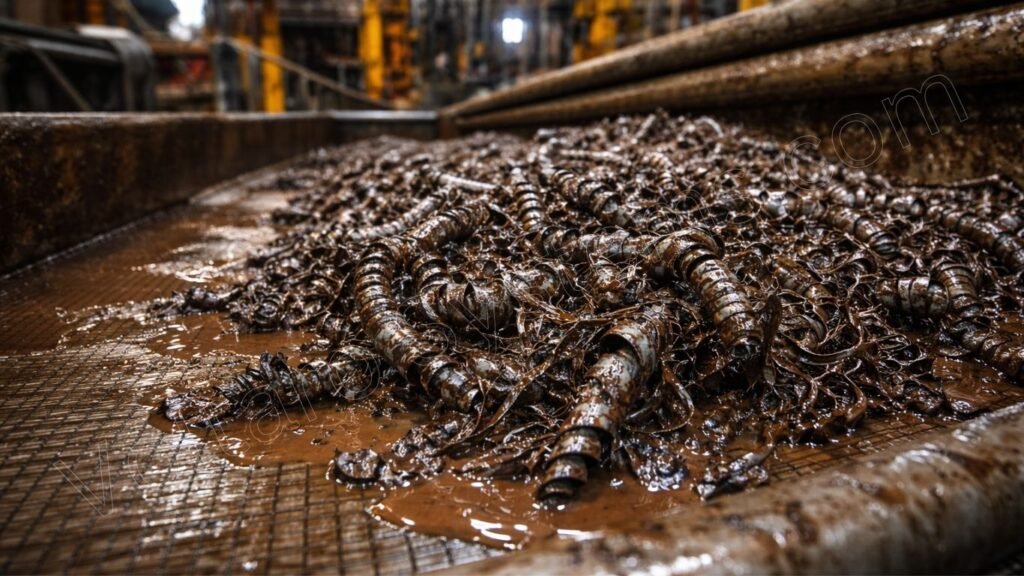
If you’ve ever cleaned a conventional ditch magnet on a milling job, you know what coarse swarf looks like: grey-black metallic shards ranging from a few millimetres down to fine metallic dust, often coated in drilling mud, clinging to the magnet surface in a dense layer that smells of hot metal and OBM.
What you can’t see is the fraction that the magnet missed — the sub-100-micron particles that stayed in suspension in the fluid, passed through the shakers with the mud, went back into the active pit, and are now heading back downhole with the next pump stroke.
Particle Size Distribution and Why It Determines Your Risk
Drilling swarf is not a uniform material. It spans a wide particle size range, and different size fractions cause different damage types through different mechanisms:
- Large particles (1–10 mm): Visible to the naked eye on the magnet surface. These are effectively captured by any neodymium rod system operating above 8,000 Gauss. They are a risk to flow restriction and junk basket integrity but are rarely the primary driver of pump or sensor damage
- Medium particles (200 µm – 1 mm): The primary driver of valve and seat wear in positive-displacement pumps. Also damaging to RSS seals and bearing assemblies. Captured effectively by modern neodymium systems at 10,000–12,000+ Gauss but may escape lower-gauss systems at high flow velocities
- Fine particles (50–200 µm): The most dangerous fraction for precision pump internals (liner bores, pistons) and for MWD/LWD sensor port erosion. Also the primary source of magnetic survey interference. Require 10,000+ Gauss for reliable capture at practical flow rates; 12,000+ Gauss provides significantly better capture efficiency for this fraction
- Ultra-fine particles (<50 µm): Poorly captured by most surface magnetic systems. Can contribute to accumulative pump wear at very high contamination levels. Some particle size in this range may remain in the fluid system even with high-gauss magnetic separation
This size distribution is why magnet Gauss rating matters for fine particle capture — not just for overall swarf removal efficiency. A system that captures 90% of the swarf by mass but misses 80% of the fine fraction is not performing as well as the mass-capture figure implies, because the fine fraction is disproportionately responsible for the most expensive equipment damage.
The “Shale Shaker Will Get It” Misconception
One of the most persistent misconceptions in swarf management is that the shale shaker will remove ferrous particles from the fluid system. It will not. Shale shakers remove particles by size — screens with mesh sizes typically ranging from 80 to 210 microns separate formation cuttings from the mud by mechanical filtration. Swarf particles in the same size range pass through the screens along with the mud because they behave identically to solids in the size cut. Ferromagnetic separation — permanent magnets — is the only method that selectively removes ferrous particles from the fluid stream regardless of particle size.
How Swarf Destroys Your Equipment — System by System
The damage mechanisms of swarf contamination are not hypothetical. They are well-documented in equipment failure reports, post-job teardown inspections, and drilling contractor maintenance records. Here is exactly what happens to each system when swarf is not managed:
Mud Pump Failure: The Most Expensive, Most Preventable Cost
A positive-displacement mud pump is a precision machine operating at high pressure and high cycle rate. It depends on tight clearances between its liner bore, piston assembly, valve, and valve seat to maintain discharge pressure. Introduce a continuous stream of abrasive metal particles into the fluid it’s pumping and you’ve converted your drilling fluid into a lapping compound.
The damage progresses through recognisable stages. First, valve seats pit and groove as the hardened swarf particles embed into the seat faces and abrade the opposing valve. Valve efficiency drops. Pump discharge pressure decreases. The driller compensates by running the pump faster. This accelerates the wear. Then liner bores expand unevenly as fine particles abrade the bore surface during each stroke. Piston faces wear and lose their seal profile. Liner replacements come sooner than expected. Eventually, a valve seat or piston fails suddenly during a critical circulation — often during a connection or during a sensitive pressure-sensitive operation — forcing an emergency shutdown.
On an offshore floater with a day rate in the $200,000–$400,000 range, a pump rebuild event costs $600,000–$1.2 million in rig time alone. Parts are additional. And the insidious part is that the root cause — swarf contamination — is almost never included in the incident report because nobody was tracking swarf volume in the fluid system.
The MWD Survey Problem: Wrong Data Is Worse Than No Data
This is the swarf damage mechanism that deserves far more attention than it receives, because its consequences can be catastrophic and are almost never attributed to the correct cause.
MWD survey tools determine wellbore azimuth by measuring the earth’s magnetic field using three-axis magnetometers. The accuracy of these measurements depends on the external magnetic environment being dominated by the earth’s field — approximately 50,000 nanoTesla at most drilling locations. When fine ferrous particles are suspended in the annular fluid surrounding the MWD tool, they create a local magnetic anomaly that distorts this measurement.
The effect is not random noise — it is systematic bias. The azimuth measured by a ferrous-contaminated MWD tool is consistently offset from the true azimuth in a predictable direction. In a section where swarf concentration in the annular fluid is high — typically in intervals near the casing shoe and in high-dogleg sections where casing wear generation is elevated — this bias can introduce azimuth errors of several tenths of a degree. Over a 2,000-metre horizontal section, a 0.5-degree azimuth error translates to a lateral position error of 17 metres — potentially enough to miss a tight reservoir target window.
The shattering irony is that this survey error is effectively undetectable in real time. The MWD tool reports a survey. The survey is plotted. The wellbore is steered on the basis of that survey. Only when the well reaches its objective — or fails to reach it — does anyone begin investigating whether the surveys were accurate. And even then, swarf contamination of the annular fluid is rarely identified as a contributing cause.
What Is Swarf Actually Costing You Per Well?
The challenge with swarf cost attribution is that swarf-related damage is diffuse. It doesn’t cause one dramatic failure that triggers an investigation. It causes slightly shorter pump life, slightly more frequent valve replacements, slightly degraded survey quality, slightly worse motor performance — each of which sits below the threshold of individual investigation and gets attributed to the nearest plausible alternative cause.
When you add it all up properly, the picture changes significantly.
The Direct Cost Stack
- Pump liner replacement frequency. If your pump liners are being changed at 6-week intervals instead of 14-week intervals, and you’re running three pumps on a well that takes 90 days to drill, you’re paying for six additional liner sets (roughly $8,000–$15,000 each depending on liner size) that you wouldn’t have needed with adequate swarf management. That’s $48,000–$90,000 in parts alone, before rig time for the liner changes.
- Valve and seat replacement. Valve seats and rubbers are consumables on any mud pump, but their replacement frequency roughly doubles under continuous swarf contamination. On a typical three-pump rig over a 90-day well, this might represent an additional $15,000–$25,000 in consumable spend — invisible in the overall well cost because valve replacements are routine maintenance.
- Motor replacement trips. A PDM motor that should last 200+ hours in a clean fluid environment may require replacement at 120–140 hours under swarf contamination. An additional round trip to replace a motor mid-section costs 8–16 hours of rig time plus the tool cost. On an offshore rig at $200,000/day, that’s $66,000–$133,000 in rig time per event.
- MWD resurveys and sidetrack risk. If a survey error from ferrous contamination forces a directional correction or, in the worst case, a wellbore sidetrack, the cost is measured in days rather than hours. A sidetrack on an offshore well typically costs $1–5 million depending on depth and rig type.
The Invisible Cost: Operational Decisions Made on Bad Data
Beyond the direct equipment costs, there is a subtler and arguably more significant cost: every drilling parameter decision made on the basis of a degraded MWD survey is potentially a suboptimal decision. Steering commands based on azimuth data that has been biased by annular ferrous contamination lead to a wellbore that doesn’t follow the planned trajectory as precisely as it should. In a tight reservoir with a 5-metre vertical target window, this matters in ways that are very difficult to quantify after the fact.
“The pump rebuild gets logged as NPT. The survey correction gets logged as directional complexity. The motor trip gets attributed to formation hardness. Swarf never shows up in the post-well report. And nothing changes on the next well.”
Swarf and Personnel Safety: An Evolving Risk Profile
The safety risk of swarf is not primarily from the swarf itself — though sharp metal particles are a hand laceration risk during direct contact — but from the way swarf has historically been managed.
The Legacy Heavy Magnet Hazard
For decades, the standard approach to swarf removal was a ceramic ferrite magnet block placed in the open flowline ditch. Cleaning this system involved physically lifting a 15–40 kg magnet block — against its own attraction force toward nearby steel structures — and manually scraping the accumulated swarf from its surface with a tool or gloved hands. This operation was performed multiple times per shift during milling operations, in confined flowline areas, often on slippery mud-contaminated surfaces.
The injury profile this created is entirely predictable: pinch and crush injuries from the magnet’s attraction force, musculoskeletal strain from repeated heavy lifts, chemical skin burns from mud-contaminated surfaces, and slip events from the working environment. These incidents are documented in rig safety records across the industry. They are also entirely preventable.
Where the Industry Is Now
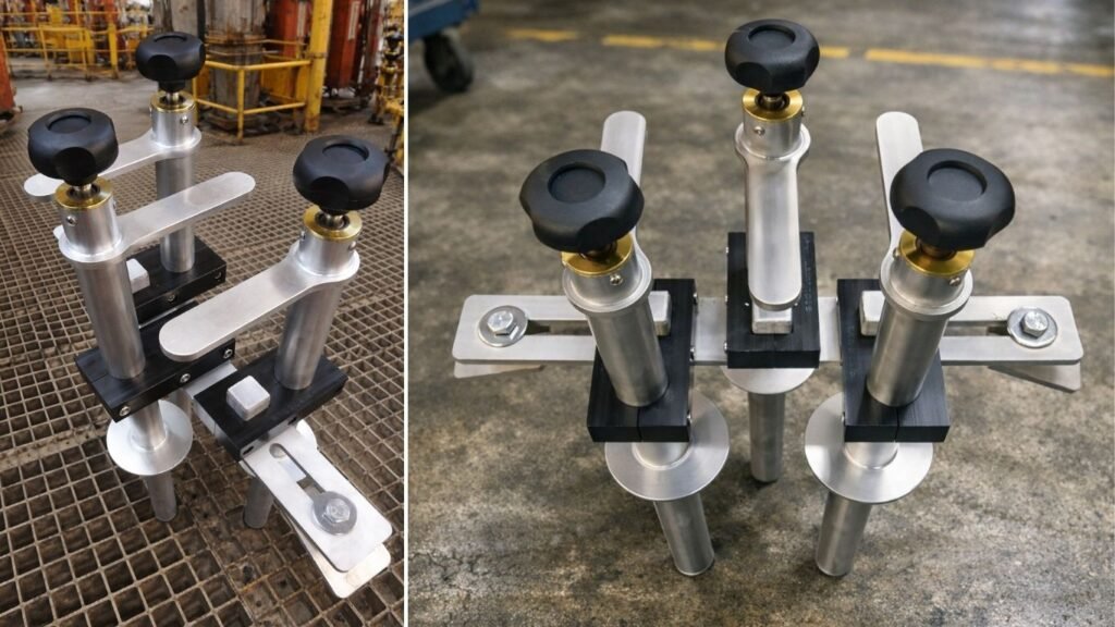
Modern neodymium rod-based ditch magnet systems have largely solved the heavy-lift hazard through lightweight rod designs (under 4 kg per rod) and zero-contact discharge mechanisms that release swarf into a collection vessel without hand contact.
What the evolving regulatory environment is now requiring, however, is more than hazard elimination — it requires documented evidence of how the task was performed. HSE management teams and operator drilling superintendents increasingly require a paper trail demonstrating that manual handling tasks were completed within zero-contact protocols. This is a documentation requirement that adds a data dimension to what was previously a pure equipment-specification decision.
Detecting Swarf: How Do You Know It’s a Problem?
The honest answer is that most operations have no real-time swarf detection capability. Swarf in the fluid system is invisible on conventional instrumentation. The indicators that suggest a swarf problem are all indirect:
- Accelerating pump wear: Liner sets requiring replacement earlier than historical average; increasing frequency of valve and seat changes; declining pump efficiency at constant SPM
- Motor performance degradation: Declining differential pressure across the motor; increasing torque for the same weight on bit; unexplained reduction in lateral penetration rate mid-section
- MWD data quality issues: Increasing spread in multi-station analysis residuals; survey corrections that are larger than expected given the formation environment; magnetic toolface instability during stationary surveys
- Post-run BHA teardown findings: Accelerated wear on stabiliser blades, RSS bearing assemblies, and PDC cutters that is inconsistent with the formation abrasivity; visible ferrous staining on tool surfaces
- Visual evidence during ditch magnet cleaning: The most direct indicator — if your ditch magnet is producing significantly more swarf per cleaning cycle than expected, the contamination level in your fluid system is high
The key insight here is that the only direct real-time swarf indicator is the ditch magnet cleaning log — specifically, the weight of swarf captured per cleaning cycle, correlated to time and measured depth. Without this data, all swarf detection is indirect, lagging, and retrospective. This is why quantitative swarf logging is not just a nice-to-have feature in a ditch magnet system — it is the only direct diagnostic channel available for swarf contamination in the fluid system.
Which Wells Generate the Most Swarf? A Risk-by-Operation Guide
Section Mill Wells — Maximum Risk
Any well involving section milling for sidetrack, deepening, or P&A must treat swarf management as a primary operational requirement. The swarf volumes are large, the generation rate is high, and the duration of exposure is typically measured in shifts rather than hours. A high-specification ditch magnet running on a 30–60 minute cleaning schedule for the full milling window is the minimum standard.
Extended Reach and Horizontal Wells — High Background Risk
Long horizontal sections with high-dogleg curves and continuous lateral loading against the casing generate persistent casing wear swarf for the full duration of the horizontal section. The generation rate is lower than milling but the duration is much longer. A ditch magnet running continuously with 4–8 hour cleaning intervals is appropriate for horizontal sections with significant lateral lengths.
Multi-String P&A Campaigns — Cumulative Risk
P&A operations involving multiple casing string mills in sequence accumulate swarf from each milling operation in the same active fluid system. The cumulative load can be substantial. Additionally, P&A operations in mature regulatory environments are increasingly required to demonstrate effective debris recovery — a documentation requirement that only a quantitative swarf logging system can satisfy.
Workover Operations — Often Overlooked
Workovers involving multiple mill-out operations — particularly in multi-zone completions where sequential frac plug removals are required — generate intermittent swarf bursts that are often not managed with dedicated magnetic separation equipment because they don’t fit the “milling job” mental model. Yet the cumulative ferrous contamination from a 10-plug workover can rival a short section milling operation.
Frequently Asked Questions About Swarf
Swarf is fine ferrous metal particles generated when steel contacts steel downhole — during section milling, drill string rotation against casing, and mill-out operations. Particles range from visible shards to sub-50-micron dust. Swarf is not removed by shale shakers; dedicated magnetic separation equipment is required.
The primary source is section milling, which produces 40–80 kg of steel swarf per 50 metres of milled casing. Secondary sources include casing wear from drill string rotation through doglegs, mill-out of float equipment and bridge plugs, and casing scraper runs.
A section mill through standard 9⅝-inch casing produces approximately 1.0–1.5 kg of swarf per metre of milled interval — 50–75 kg per 50-metre section. At a typical milling rate of 3–4 m/hr, a 16-hour shift generates 40–60 kg entering the active fluid system.
Ferrous particles recirculated through the pump act as abrasive slurry against liner bores, valve seats, and pistons. This reduces pump life from 120–150 days to 40–60 days under heavy contamination, leading to unplanned rebuilds and NPT.
Yes. Fine ferrous particles in the annular fluid create a magnetic anomaly around the MWD tool, introducing systematic azimuth error. Over a 2,000-metre horizontal section, a 0.5-degree bias can cause a 17-metre lateral position error — enough to miss a tight reservoir target.
Drill cuttings are non-magnetic rock fragments separated by shale shakers. Swarf is ferromagnetic metal particles that pass straight through shaker screens — regardless of size. Only magnetic separation equipment removes swarf from the active fluid system.
No. Shale shakers separate solids by size, not material type. Swarf particles in the same size range as formation cuttings pass through the screens identically. A ditch magnet is the only equipment that selectively removes ferrous particles from the fluid stream.
In high-concentration scenarios during aggressive milling, swarf accumulation around the mill and BHA can contribute to stuck pipe and pack-off events. Adequate circulation rate and continuous surface magnetic separation are the primary preventative measures.
The most direct indicator is swarf weight per ditch magnet cleaning cycle. Indirect signs include accelerating pump wear, increasing valve replacement frequency, declining motor performance mid-section, and MWD survey anomalies. Without a swarf logging system, the root cause is rarely identified.